For years I have been advising customers to setup disaster recovery and high availability for their Oracle Database systems, I never had the opportunity to practice what I preach for my home network/storage. My NAS devices were separated by two floors on the same network. Luckily I was finally able to move one of my NASes to a backup site.
Both sites have a Ubiquity Cloud Gateway and support Unifi SD-WAN making the setup of site to site VPNs very easy.
More on how to set this up here
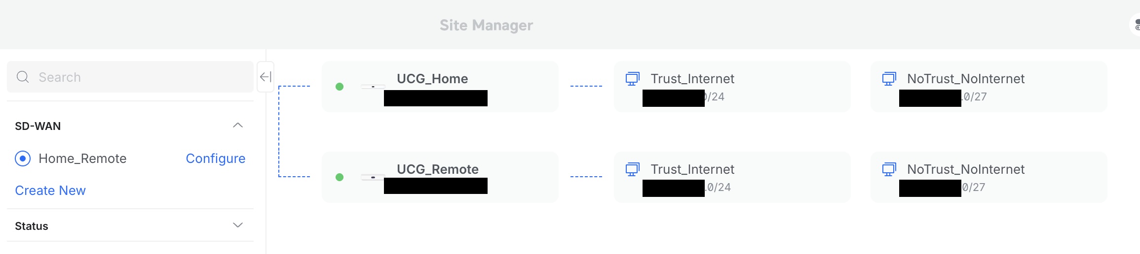
It is a general best practice to approach network security as an onion, setting it up in layers and separate traffic. On network level you do this with separate isolated networks, implemented by VLANs and firewall rules.
In my case I created a few VLANs :
- NoTrust_Internet
- NoTrust_NoInternet
- Trust_Internet
And of course the Default VLAN (1) for managing the Unifi setup.
I use a zone based firewall approach and created a zone for every VLAN I created
On the primary site, backups are taken to the local NAS, I then use snapshot replication to the remote NAS. One leg of the NAS is in a VLAN with Internet access, to allow for updates and another NIC is bound to the NoTrust_NoInternet VLAN.
I wanted to do the remote replication over the NoTrust_NoInternet VLAN.
I created this VLAN (Network in Unifi), and specified “Isolate Network” this means that by default Firewall rules are created to isolate this network completely, I also made sure the “Allow Internet Access” tickbox was not set.
Firewall rules
This is how I set it up
On Site A you need following firewall rules (of course limit is further by specifying source/ destination ports) :
| Rule | Action | SourceZone | Source | DestinationZone | Destination |
|---|---|---|---|---|---|
| SiteA_VPN | Allow | NoTrust_NoInternet | NAS_A | VPN | SiteB |
| VPN_SiteA | Allow | VPN | SiteB | NoTrust_NoInternet | NAS_A |
And then following rule for SiteB
| Rule | Action | SourceZone | Source | DestinationZone | Destination |
|---|---|---|---|---|---|
| SiteB_VPN | Allow | NoTrust_NoInternet | NAS_B | VPN | SiteA |
| VPN_SiteB | Allow | VPN | SiteA | NoTrust_NoInternet | NAS_B |
I thought that this was enough, unfortunately that wasn’t the case, I could ping the gateway on SiteB from NAS_A but not NAS_B itself.
What needs to be added is following :
Site A
| Rule | Action | SourceZone | Source | DestinationZone | Destination |
|---|---|---|---|---|---|
| NoTrust_VPN | Allow | NoTrust_NoInternet | NAS_A | VPN | NAS_B |
| VPN_NoTrust | Allow | VPN | NAS_B | NoTrust_NoInternet | NAS_A |
Site B
| Rule | Action | SourceZone | Source | DestinationZone | Destination |
|---|---|---|---|---|---|
| NoTrust_VPN | Allow | NoTrust_NoInternet | NAS_B | VPN | NAS_A |
| VPN_NoTrust | Allow | VPN | NAS_A | NoTrust_NoInternet | NAS_B |
You can set this up by either specifying the individual IP or more broader a network range, make sure to limit the ports being used as well.
Note that since you have two legs per NAS in two seperate networks, you need to add a route on the NAS devices as well.
I specified that to go to SiteB from NAS_A the Gateway on SiteA needed to be used.
for exampe
If siteA has follwing network 192.168.42.0/24 and siteB has network 192.168.66.0/24
the route on NAS_A would be
Network destination : 192.168.66.0
| Network Destination | 192.168.66.0 |
| Netmask | 255.255.255.0 |
| GateWay | 192.168.42 |
| NetworkInterface to use | Network interface attached to NoTrust_NoInternet VLAN |
It took me a while to figure that out, I hope this helps you when you are implementing a similar setup.
Happy networking